
Much has been written about Viktor Schauberger’s Repulsine, an invention that was shelved, and that no one, since that time, has been able to reproduce.
I recently came across a description that reminded me of the research into Schauberger technological developments I did in the late 1980s and early 1990s. The article shows that today, we are no closer to understanding the secret of this particular Schauberger invention than we were back then.
Here is the article and my comments to it.
A BOINC project proposal, analysis of Viktor Shaubergers repulsine A and B https://boinc.berkeley.edu/forum_thread.php?id=8252
Does anyone know if the Repulsine mod A and B has undergone Computational fluid dynamics simulations to determine the best dimensions for the platters, their spacing, the number of slots and their shape and the shape of the “waves” in the platters, and other
dimensions ?
Has it been studied for the generation of electrostatic fields ?
I have seen pictures of these units, and the outer shell and almost all parts is made of copper.
Some pictures and diagrams of the type A:
http://jnaudin.free.fr/html/repulsin.htm
Type B:
http://jnaudin.free.fr/html/repulsb.htm
These devices are interesting, and the alleged properties also.
About these devices:
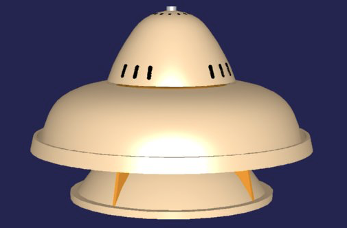
This saucer was composed of a number of copper plates bolted together. Air was drawn in at the to and into the rapidly spinning saucer which was set into motion by an electric motor. In this machine no paddles pushed upon the air to start it. Instead, a motor was used to spin the whole saucer model to the desired number of revolutions per minute.
The air was thus spun rapid over channels formed by the upper and lower surfaces of two copper plates. On these plates alternate ridges and depressions on both plates kept the air moving in snake-like wave forms and it moved toward the periphery of the saucer. Because the saucer was rapidly spinning, the air was folded over upon itself as it moved laterally into many individual vortices. The air was rotating in these vortices and moving up and down between the ridged plates.
The air was cooled and made more dense as it progressed towards the periphery. At and around the saucer the periphery, it was ejected into the atmosphere at great speed.
The vortex chamber becomes a kind of high-voltage electrostatic generator due to the air particles in high speed motion acting as an electrical charges transporter.
In this machine, centripetal air flow changes to centrifugal air flow at this periphery. The air, once outside the saucer, spirals away in a centrifugal motion. It is at this periphery, at the midline of the saucer, where the change of motion takes place.
Sometimes the Coanda Effect is cited as a reason this saucer flew. Coanda effects, if present at all, are only a secondary force if Viktor Schauberger’s calculations are correct. Coanda effects alone could never be powerful enough to generate the lifting force equal to 228 tons which Schauberger estimated his small model produced.
The history of the Schauberger flying disc models is as follows. According to Alexandersson, Aloys Kokaly, a German, began work for Viktor Schauberger in the early days of the Second World War producing certain parts for a “flying object” which were hard to obtain in Austria. The parts were to be delivered to the Kertl Works in Vienna which was the site of this work at the time. The Kertl Works were operating “on higher authority” in association with Schauberger. Kokaly was received at Kertl by its chief and told by this individual, somewhat bitterly, that one of these strange contraptions had already flown.
The purpose of this device was twofold. First, it was to investigate free energy production. This could be done by running a shaft to the rapidly rotating wheel-like component which was auto-rotating at between 10,000 and 20,000 rpm. The wheel component had to be spooled up with a fast rotating electric engine first. Using reduction gearing, some of that energy could be mechanically coupled to an electric generator producing electricity at no cost. The second purpose of these experiments was to test Schauberger’s theories on “levitation” and flight.
Two prototypes were said to have been built at Kertl. The test flight was done without Schauberger’s presence or even his permission to do the test. The model flew as described above but it did considerable destruction to the Kertl Works so there were mixed feels concerning the success of this flight. The force of levitation was so strong that it sheared six 1/4 inch diameter high-tensile steel anchor bolts on its
way to the roof. One of these prototypes does exist today, in Germany.
So, is this a viable project ?
The problem is that i do not have any programming skills, and i do not have the required knowledge of mathematics.
End of BIONC project proposal —
My take (Sepp) on this is as follows:
I studied Schauberger pretty intensively in the 1980s and 1990s, and in my view, the principle Schauberger was trying to demonstrate was that of a self sustaining vortex formed at the top of the machine, “drawing” the machine in the direction of lift. In that sense, the name “Repulsine” is a bit of a (perhaps intentional?) misnomer. It might have been chosen to keep this tech from falling in the wrong hands?
Vortices are really powerful and in the right conditions can be self-sustaining. In the case of the Repulsine, the prototype actually got lost, flying destructively right through the roof out of the laboratory, after breaking its moorings…
This could be a simple and rather powerful lift generating apparatus if properly evaluated and built to exacting specifications.
There are various diagrams of the repulsine available in a net search, however none of those diagrams seem to show the air flow correctly. In my view, a powerful air vortex forms above the machine, which draws the machine into it. The exiting air flow in small vortices, out the side and downwards of the machine, could be harnessed for directing the flight. It does not curl back under the machine to provide lift, as this (incorrect) diagram seems to imply.
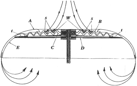
The effort in evaluations and attempted replications seems to concentrate on a push by the exiting air, a repulsive force as the name repulsine might indicate, but that is not the force Viktor was after. His repulsine is not similar to a jet, instead there is a suction effect as a result of the fast inflowing rotating air forming a powerful EXTERNAL vortex above the machine, which the machine can “fall into” almost as if it fell into an overhead gravity well or was drawn upwards by a powerful tornado.
Naudin (see links above) locates the vortex inside the machine and he argues pressure. In my view, he doesn’t have that correctly either.
Schauberger was envisioning the same principle to work in water, for ship or submarine propulsion. Again here, no one seems to have caught on to the possibility of an external water vortex in front of the motor being produced by the rotating intake. That would be the real driving – or rather attracting – force of such an underwater propulsion system. This could turn out to be vastly superior to the current method of ship propulsion with screws, and also superior to the currently projected and used water jets.
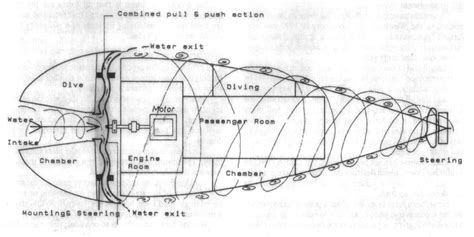
Also here, the essential part, the pulling water vortex in the front, is omitted in favour of emphasising a pushing action of the trailing vortex on the conical body.
I hope someone will take up where Schauberger left off on this invention and put the vortex action of both air and water to good use.